Home | Hardware Plan | Hardware | Graphical User Interface | Human Interaction | Design | Reflections
Hardware
Contents
Intoduction
Hardware makes up a large portion of our robotics project from 3D printing, soldering, drilling, building and much more. Below I demonstrate the key things that we did that outline what we learnt whether they work or were a disaster.
Solder
Soldiering was very important for the project as we needed to supply our raspberry pi with 5 volts of electricity, but this was coming from a battery that read 12.9 volts on the multi-meter. If we plugged this in directly to the Pi it would overwhelm it and in return destroy the PI (This happened btw). To get around this issue we needed something to step the voltage down to 5 volts. Below is a video of me soldering a chip that we were going to put on a breadboard as our voltage converter. This did not go to plan and instead we got another chip and soldered 4 wires to it. This was better than the chip and breadboard setup as it was more modular. The new voltage converter allowed you to change the voltage that it was passed through by turning a small dial, this made it very helpful when we were running into problems with 5 volts not being enough for the raspberry pi and touch screen. Because of this we turn the dial to the right a small amount giving the pi 5.2 volts which in doing so removed the warning on the screen saying there was not enough power.
Component Housing
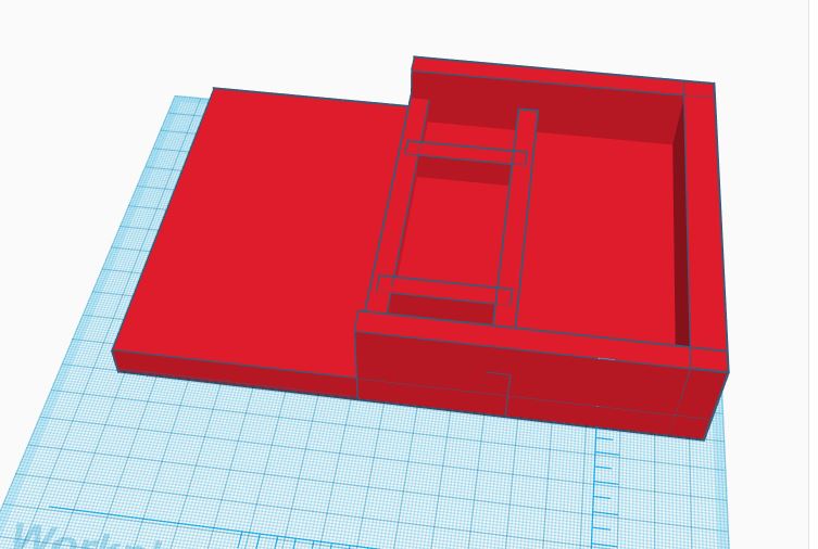
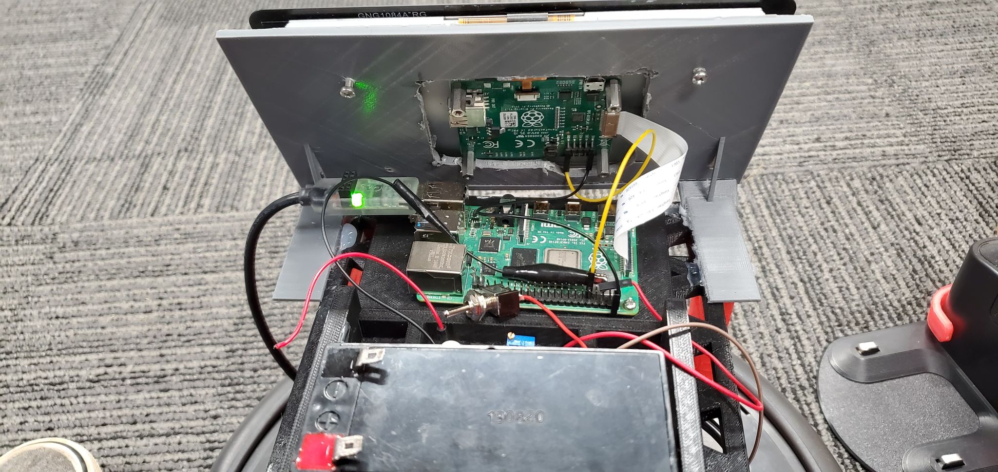
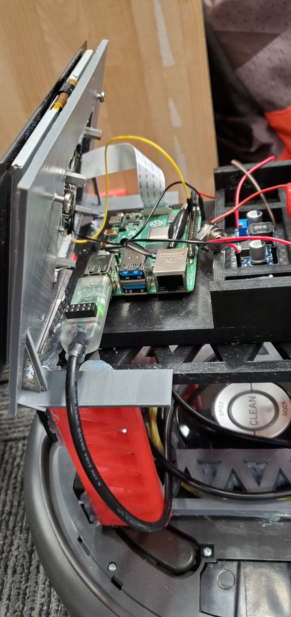
To store our Raspberry pi, voltage converter and battery we created a sketch and 3D printed a holder, this can be seen below. After we put this together, we decided to wire in a switch so you could use that to turn the voltage converter on and off and in doing so the Raspberry pi and the touch screen.
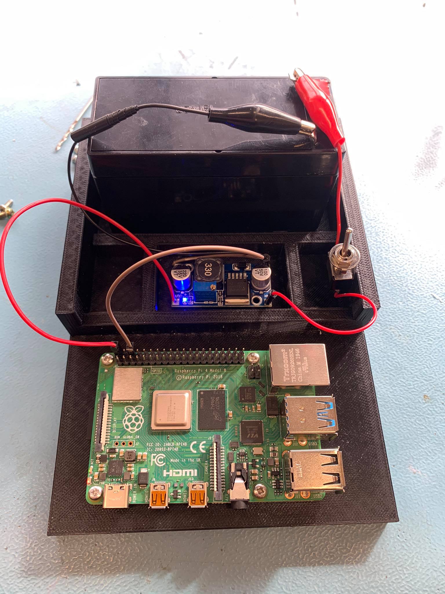
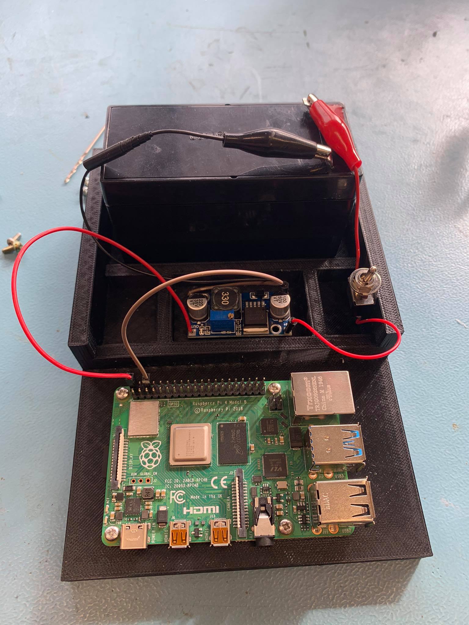
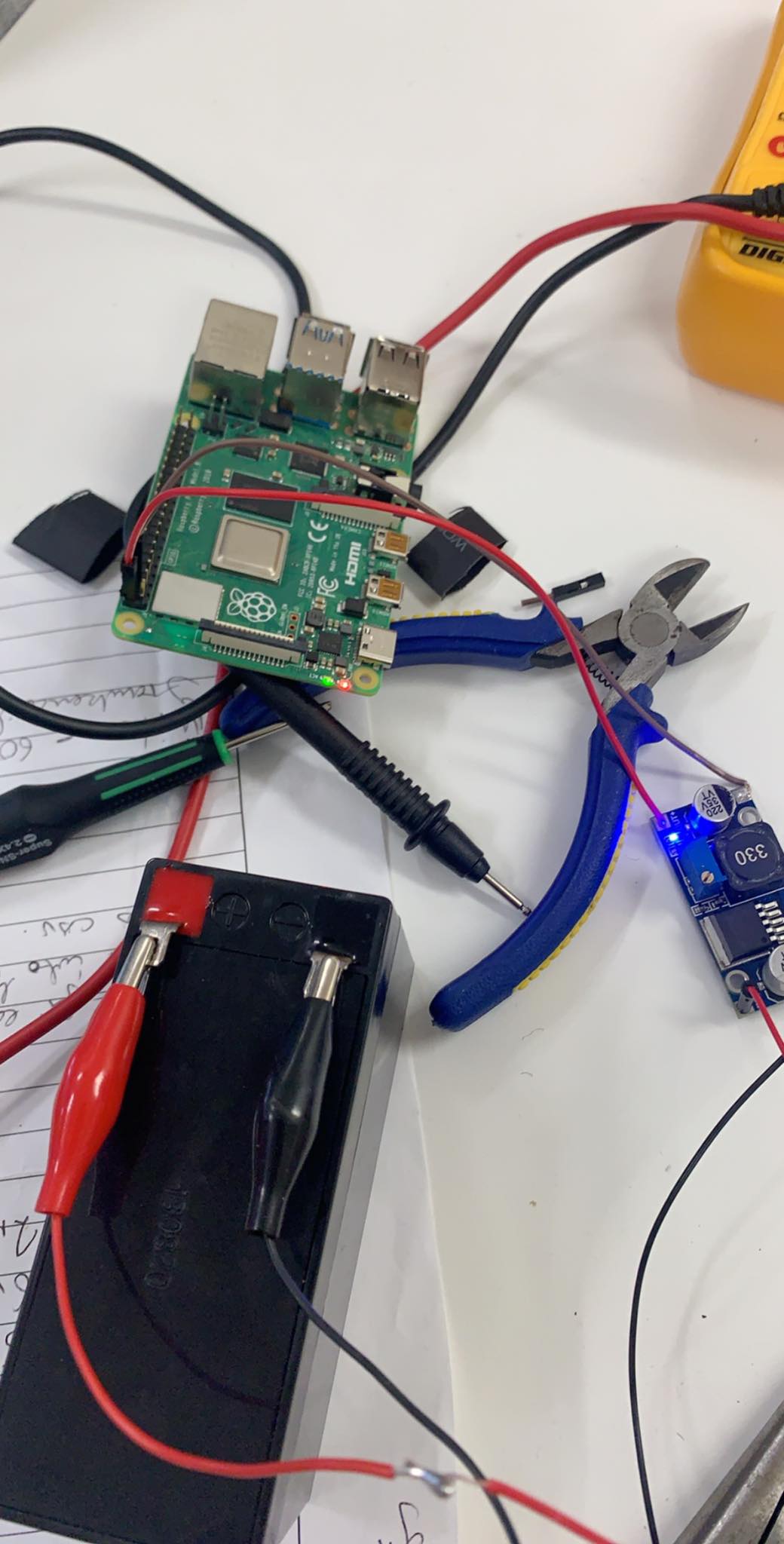
This is our first test to make sure the battery was correctly powering the raspberry pi before we secured all the hardware into the housing
The pictures above show the component housing in its 2 states, on and off. The other image is of the prototype that was to be 3D printed. The idea was to separate each component to make it look cleaner and to give us some space to route cables. It was not until after all the components were installed that we decided to put in a switch, but this was great idea.
Here is a video of the switch in action:
3D Printing
A big part of our project relied on the 3D printers such as girders, mounts, holders and the component housing. Some of this didn’t go as planned. The girders were printed off earlier in semester when we weren’t having issues with the printers, but this quickly changed. After that a lot of our prints were interrupted by either the filament snapping or the nozzle blocking and with the Dremel if this happened the head needed to be pulled apart which took a few hours. This was diffidently a big road block in our overall productivity, especially when some of the items we were printing were taking 12 hours at a time and if anything was to go wrong during this process you would have to start from scratch again.
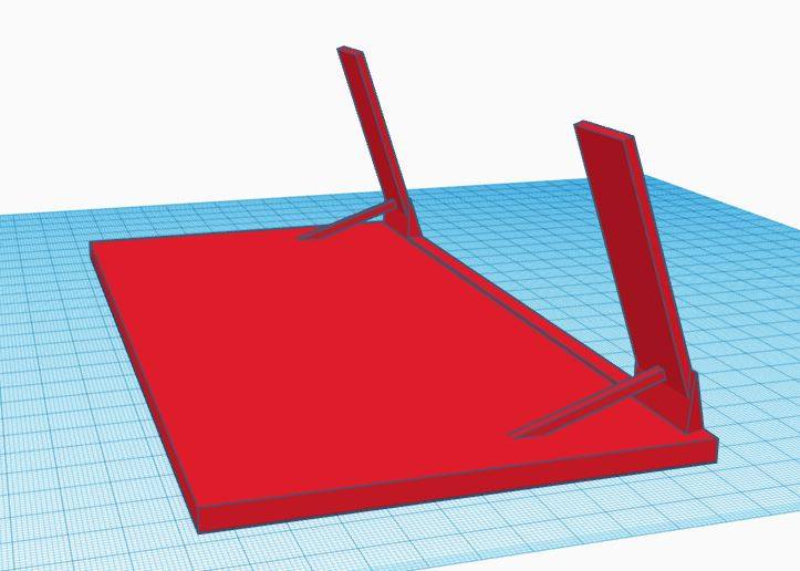
- This is the sketch for the screen holder before it was printed.
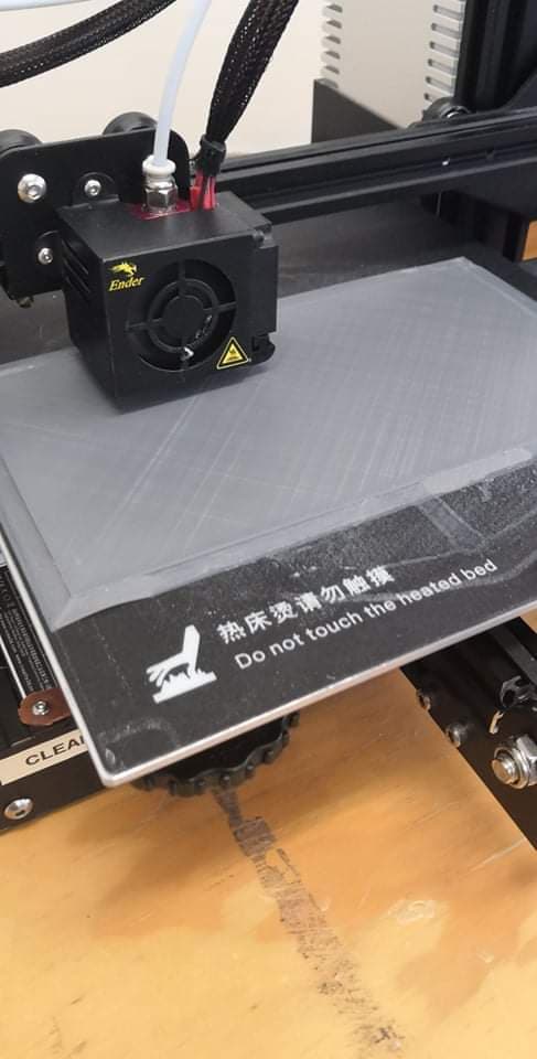
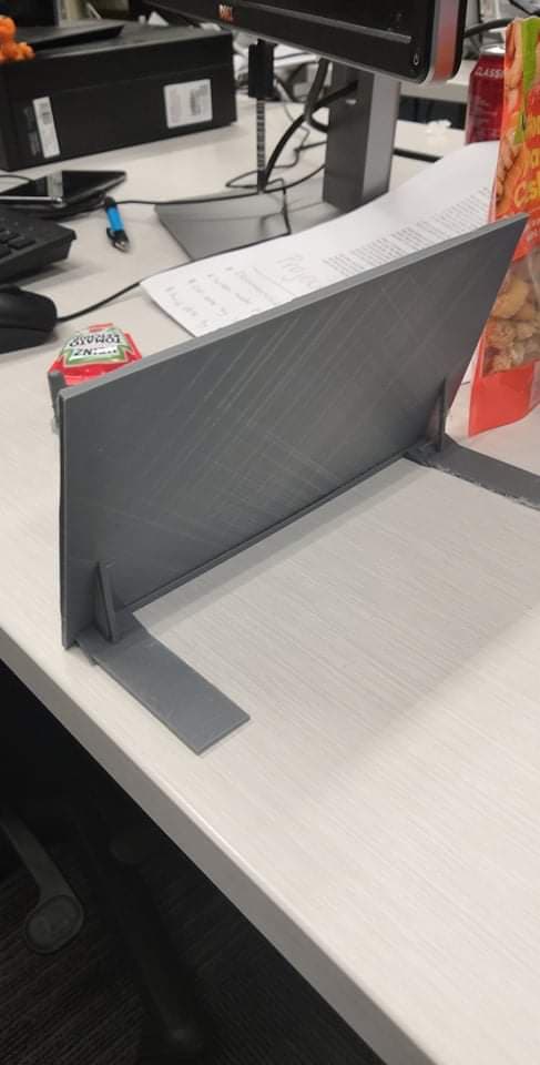
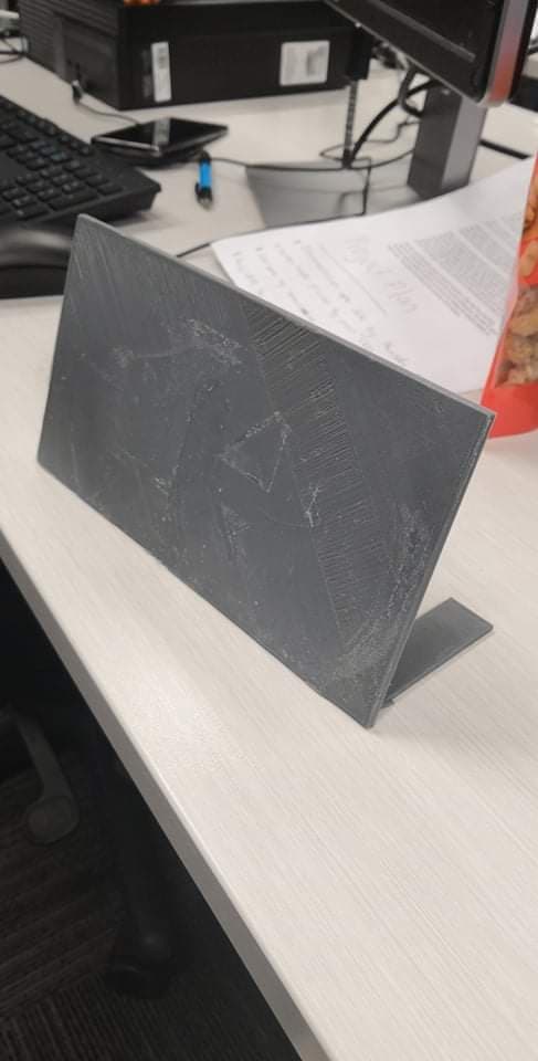
- Below is the process from start to finish of the screen holder being printed.
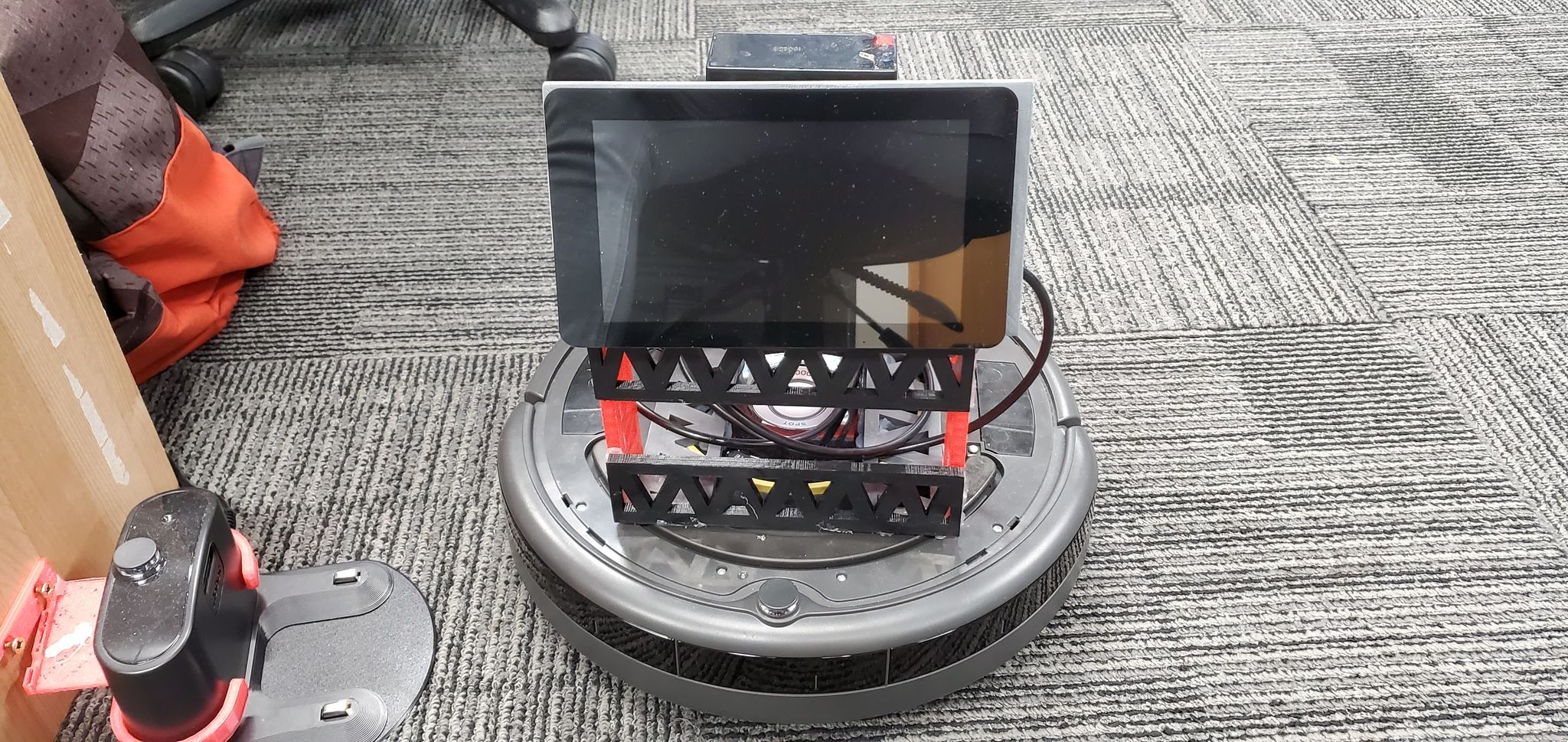
- This is Dot once we had the touch screen mounted to the holder and attached it to Dot.
- View from behind the robot with the hole we cut into the holder to attach the screen
- Side view
- Front view
Dot Connected to the PC
This was the fist time we had dot driving around, this was before we started using the Raspberry Pi and just had the IRobot connected through a USB port.
Dot Connected to Pi
After working out how do worked from testing it on a PC we moved to getting the raspberry pi hooked up and testes the robot with this. This was a big step as we got the software working on Raspbian which is the OS for the Pi. The only small problem we ran into was different versions of python, but more details about that in another section.
Our First Prototype
This was our first prototype with everything put together so we could test everything and see if it functions how we had planned and imagined.
Final Product
Although we are not happy as a group with what we have achieved with Dot we have to take into perspective that we only just started tinkering with Dot at the start of second semester. We had no idea what was instore for us with the IRobot and how it would function until we dug deeper into it. We managed to come a tremendous distance so I feel we should be proud of what progress we achieved. Our final build consists of our robot being able to be driven using a small controller. Its foundation is the IRobot itself and from that we build a frame using 3D printed girders. In total we used 12 girders which we build a box as support. On top of this box is where the component housing sits with all the electronics encased inside. Infront of this is where the screen mount it fitted. Everything is currently held together using hot glue and a silicon-based glue. This makes the overall structure weak but it was only planned as the prototype. Our final goal was to get into contact with the engineering department and build a shell that would cover Dot using vacuum forming.